English
 Pусский
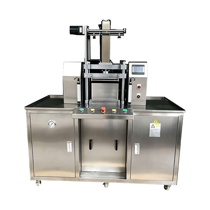
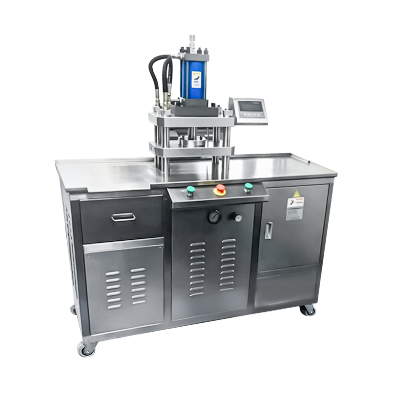
Servo Driven Cosmetic Powder Pressing Machine
A pressing platform in which the compaction stroke is generated by a servo motor and ball screw assembly rather than a hydraulic or pneumatic circuit. Position, speed, and force are controlled through the drive parameters, allowing the pressing profile to be shaped stage by stage. Applied to cosmetic powder compaction where cycle repeatability, force accuracy, and process documentation are specified requirements.
Digital Force Control
Force is generated by the servo drive torque and verified by a load cell under the die plate, so the pressing value is defined in software rather than by a pressure regulator setting.
Profile Repeatability
Each stage of the pressing profile is stored in the recipe, and the drive reproduces the same motion curve from cycle to cycle regardless of production duration.
Process Data Capture
Position, velocity, torque, and force are recorded at a fixed sampling rate for every cycle, and the curve data is stored against the batch record for review.
Servo Pressing Profile
The stroke is divided into programmable stages, each with its own speed, position, and force target.
Stage 1
ApproachRam descends at a defined velocity to a position just above the powder surface. Approach speed is set higher for short cycle times and lower for embossed tooling.
Stage 2
ContactVelocity is reduced at the point of contact to limit impact on the powder bed and preserve pan edge geometry at the start of compaction.
Stage 3
CompactionForce rises to the target value at a controlled rate. The compaction gradient is set per formulation to control density distribution through the cake.
Stage 4
HoldForce is maintained within a tolerance band for a defined interval, allowing the powder matrix to settle and the binder to flow between particles.
Stage 5
ReleaseForce is reduced gradually rather than released instantly. Gradual release reduces the pressure differential between the punch and the cake surface.
Stage 6
RetractRam returns to the top position at a set velocity, clearing the die area for the ejection stage and the next fill cycle.
Drive Train and Measurement
Components that determine force accuracy and cycle repeatability.
Servo Motor
AC servo motor rated for continuous pressing duty. Torque output is mapped to pressing force through the ball screw pitch, and the drive holds torque within a closed loop during the hold stage.
Ball Screw and Ram
Preloaded ball screw converts rotation to linear motion with low backlash. The ram is guided on linear rails to limit lateral deflection under load and to keep punch alignment within tolerance.
Load Cell
Strain gauge load cell mounted under the die plate measures actual pressing force. The signal is sampled continuously and compared to the recipe target during the compaction and hold stages.
Position Encoder
Absolute encoder on the servo motor provides ram position feedback with high resolution. Position values define stage transitions and are recorded with the force curve for each cycle.
Technical Data
Standard frame values. Force range, stroke, and tooling are defined per application.
Applied Production Cases
Product formats and process conditions suited to servo driven pressing.
Dense Pigment Compacts
Formulations requiring a defined compaction gradient benefit from stage level control, which reduces capping on high density pans.
Multi Layer Compacts
Sequential fill and press stages with distinct profiles produce two or three layer cakes with controlled interlayer density.
Powder Foundation
Binder rich powders pressed with gradual release to limit surface cracking and improve pan edge stability.
Embossed Pan Format
Relief and logo patterns preserved through reduced contact velocity and controlled compaction gradient.
Baked Cake Preform
Large format cakes pressed at moderate force with extended hold time to establish uniform density before the baking stage.
Regulated Production Lines
Process environments where per cycle force and position data must be retained for batch documentation and deviation review.
Frequently Asked Questions
Common questions raised during evaluation and line integration. Select a question to expand the answer.
How does servo pressing differ from hydraulic pressing
Servo pressing generates force through motor torque and a ball screw, so stroke position and velocity are controlled directly by the drive. Hydraulic pressing generates force through fluid pressure, which is efficient at high force but less precise on position. Servo pressing is selected where profile repeatability and cycle level data capture are required.
Can the pressing profile be changed between products
Yes. Each product recipe stores its own stage count, stage positions, velocities, force targets, and hold times. Recipes are recalled from the HMI, and changeover does not require mechanical adjustment of the drive train.
What data is recorded for each pressing cycle
Force, position, velocity, and drive torque are sampled at 1 kHz and stored per cycle. The data is linked to the batch record and can be exported through OPC UA or CSV for process review or customer documentation.
Is the machine suitable for high force applications
The standard frame covers up to 25 tons. Above this range, hydraulic pressing is normally specified. Servo pressing is selected for accuracy and process control rather than maximum force capacity.
What maintenance does the drive train require
Ball screw lubrication is verified at defined intervals, typically every 1,000 hours of operation. Linear guide rails are cleaned and re greased at the same interval. Load cell calibration is recommended every 12 months, and encoder battery replacement follows the drive manufacturer schedule.
How does the machine behave on a power interruption
On power loss, the servo drive enters a controlled stop and the ram holds position until the brake engages. Recovery procedure requires a homing cycle before production resumes. Cycle data for the interrupted unit is flagged in the log.
Can tooling be shared with hydraulic or pneumatic machines
Tooling sharing depends on the mounting interface and force range. Where the same standardized plate is used and the force range covers the required compaction force, tooling sets can be transferred with documented clearance values.
What determines cycle output on this platform
Cycle output depends on stroke length, stage velocities, hold time, and pan size. Reduced approach velocity and extended hold time lower the output rate, while short profiles on shallow pans produce higher output. Actual rates are verified during factory acceptance testing.
Process Deviation Reference
Situations observed during servo pressing and the corresponding corrective actions.
Force curve deviates from stored profile
Review the curve against the reference profile in the HMI. Check the load cell signal for drift against a reference instrument. Confirm powder fill weight is within tolerance and verify the ball screw lubrication status.
Servo drive reports torque overload
Check for mechanical obstruction in the die area and confirm the ram moves freely through the stroke. Verify the force target has not been set above the frame rating. Inspect the ball screw and guide rails for contamination or insufficient lubrication.
Position repeatability drifts over a shift
Confirm the drive cabinet cooling is functioning and that ambient temperature is within specification. Check the encoder coupling for backlash. Run the homing cycle and compare the position values against the commissioning record.
Cycle time exceeds recipe target
Review the stage velocity settings against the recipe. Check for mechanical friction in the ram guide and verify lubrication intervals have been observed. Confirm the drive is not in a torque limiting mode during the compaction stage.
Pan edges crack after compaction
Reduce the compaction gradient in the affected stage to slow force rise. Extend the hold time by 0.5 to 1 second. Verify punch and die clearance and confirm powder moisture content remains within the recommended band.
Cycle data is missing from the batch log
Check the communication link between the PLC and the data logging system. Verify storage space on the logging device. Confirm the cycle counter has not been reset and inspect the PLC clock for synchronization with the plant network.
Integration Notes
Factors that affect installation, utilities, and long term performance.
Power Quality
The servo drive benefits from a stable supply with low harmonic distortion. Where the plant supply carries significant variation, a line reactor or active filter is recommended to protect drive electronics.
Floor and Vibration
The machine requires a level floor with anchoring points per the installation drawing. Isolation pads reduce transmission of reaction force into surrounding equipment and improve position stability.
Cabinet Cooling
The drive cabinet is air cooled and requires clearance for airflow around the enclosure. Ambient temperature at the cabinet intake should remain within the drive specification throughout the shift.
Network and Data
The controller supports OPC UA and CSV export. Network configuration is defined during commissioning to match the plant MES or historian architecture, with batch identifiers mapped to the production records.