English
 Pусский
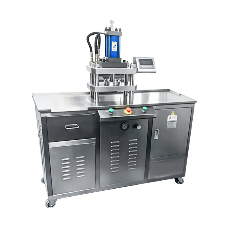
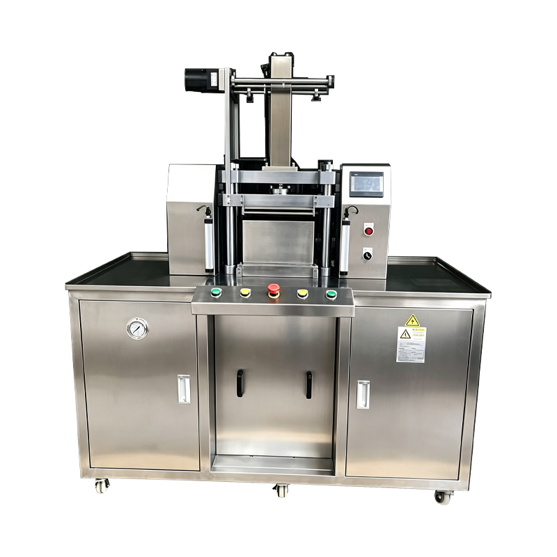
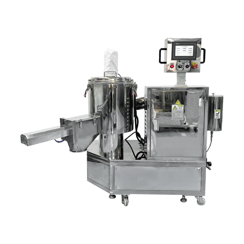
Hydraulic Cosmetic Powder Pressing Machine
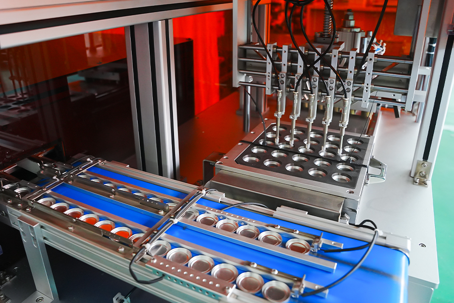
A hydraulic pressing platform built for compacting loose cosmetic powder into solid cakes and pans. The hydraulic circuit delivers high force with a controlled pressure curve, allowing dense compaction of formulations that resist mechanical pressing. The machine is applied to eyeshadow, blush, foundation, highlighter, and pressed pigment production where cake hardness and surface finish are controlled parameters.
Hydraulic Force Delivery
A closed loop hydraulic circuit maintains pressure through the compaction stroke, so dense formulations reach target cake hardness without repeated pressing cycles.
Programmable Pressure Curve
Approach, compaction, hold, and release stages are configured separately on the HMI, allowing the pressing profile to match the flow behavior of each formulation.
Thermal Stability
Hydraulic oil is held within a controlled temperature band through an oil cooler and heater circuit, keeping viscosity and force response consistent across long production shifts.
Force Data Logging
Force, position, and hold time are recorded for each cycle and stored against the batch record, supporting process traceability and deviation review.
Hydraulic System Architecture
Key assemblies that determine pressing behavior and process control.
Power Unit
Variable displacement pump with proportional valve control. Pressure is regulated through closed loop feedback from a load cell mounted on the pressing ram. Oil reservoir includes filtration, level monitoring, and temperature control.
Pressing Ram
Hard chrome plated cylinder with guided motion to limit lateral deflection under load. Stroke length and approach speed are set through the control system, and the ram can be positioned in fine increments for shallow pan formats.
Tooling Interface
Upper punch, lower punch, and die are mounted on a standardized plate. Tooling sets are interchangeable between machines of the same frame size, and clearance values are documented for each product format.
Control Cabinet
PLC, servo drive, and safety relay housed in a separate cabinet. The HMI provides recipe management, pressure curve editing, alarm history, and production counters. Data can be exported through OPC UA or CSV.
Safety Circuit
Category 3 PLd guarding with interlocked doors, dual channel emergency stop, and light curtain protection at the manual load and unload opening. Hydraulic pressure is dumped on any guard breach.
Technical Data
Standard frame values. Force range and tooling are specified per application.
Applied Formulations
Powder types and product formats handled by hydraulic pressing.
High Density Eyeshadow
Dense pigment blends that require sustained force to reach target hardness. Multi stage pressure curves reduce capping and edge cracking on deep pans.
Powder Foundation
Compacts with higher binder content benefit from controlled hold time, which helps the binder flow through the powder matrix before release.
Pressed Pigment
Heavy pigments and mineral blends pressed at low approach speed to limit powder displacement during the compaction stroke.
Baked Powder Cakes
Large format cakes pressed at moderate force with extended hold time to achieve uniform density before the baking stage.
Embossed Pan Formats
Pans with surface relief pressed at reduced approach speed to preserve detail on the upper punch face.
Multi Layer Compacts
Sequential filling and pressing stages form two or three layer compacts with controlled interlayer density.
Process Deviation Reference
Common hydraulic pressing situations and the corresponding corrective actions.
Force drops below setpoint during hold
Check the proportional valve response and confirm the load cell zero point. Inspect hydraulic oil temperature, which should remain within the 35 to 50 degrees Celsius band. Verify the accumulator precharge and inspect the pressure relief setting against the machine record.
Cake hardness varies between cycles
Confirm the hold time value has not drifted in the active recipe. Verify fill weight consistency through the inline check weigher. Inspect the upper punch face for powder build up, which changes the effective compaction gap.
Oil temperature rises above operating band
Check the oil cooler flow and confirm the cooling circuit is not blocked. Inspect the reservoir level and top up with the specified oil grade. Reduce the cycle rate temporarily if the ambient temperature is above the design range, and verify the temperature sensor reading against a reference instrument.
Ejection leaves pan seated in die
Verify the ejection stroke matches the die depth for the current tooling set. Inspect the ejector plate for wear or misalignment. Confirm the lower punch returns fully before the next filling stage and check hydraulic pressure at the ejector circuit.
Ram movement is not smooth
Inspect the guide rails for contamination and verify lubrication. Check the cylinder rod surface for scoring. Confirm the proportional valve is not sticking and review the alarm history for any pressure spikes recorded during the stroke.
Hydraulic alarm during the cycle
Read the alarm code on the HMI and check the associated sensor. Verify oil level, filter differential pressure, and temperature. Confirm the emergency stop circuit is closed and reset the alarm at the control panel before resuming production.
Deployment Notes
Factors that affect installation, operation, and long term performance.
Foundation Requirements
The machine requires a level floor with vibration isolation rated for the maximum pressing force. Anchoring points are specified in the installation drawing to limit deflection under load.
Hydraulic Oil Selection
Oil grade is selected based on the ambient temperature range at the installation site. The specified grade is recorded in the maintenance manual and must be used during top up and oil changes.
Tooling Storage
Punch and die sets should be stored in dedicated racks with protective coating. Storage conditions and handling procedures are documented to preserve surface finish between production campaigns.
Maintenance Intervals
Recommended schedule covers oil analysis every 1,500 hours, filter replacement every 2,000 hours, punch and die inspection every 500 hours, and load cell calibration every 12 months.